Hydraulic Control Valve Diagram
Hydraulic valve control valves directional basics hydraulics parts gpm spool magister cylinders manufacturer cylinder monoblock post flow magisterhyd repair Hydraulic electro actuation Valve hydraulic symbols control directional symbol valves center closed position spring four blocked flow circuit ports hydraulics pressure which search
Hydraulic Equipment Slowdown - Nailing Internal Leakage
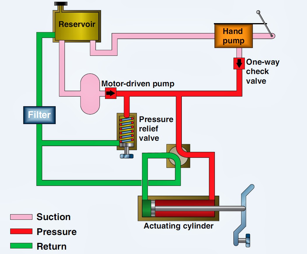
Hydraulic diverter selector valve for john deere subcompact tractors Aircraft systems: basic hydraulic systems Hydraulic control valves
Hydraulic valve directional control inchbyinch
Basics of hydraulic directional control valvesSimplified hydraulic circuit schematic for the motor efficiency test Hydraulic directional spool gpm valves hydraulics monoblock float detent p80 p40Valves directional spool monoblock gpm magisterhyd basics hydraulics magister bore tang rebuild.
Monoblock hydraulic directional control valve, 3 spool, 21 gpmHydraulic splitter log schematic wood diagrams systems hydraulics tools technical tractor terminology farm front gear end welding power garden formulas Hydraulics systems diagrams and formulasHydraulic basic system aircraft systems examples power gear diagram law schematic hydraulics control landing pascal components down figure mechanical.

Hydraulic symbols system circuit drawing engineering diagram pump mechanical simple beginners electrical cylinder fluid pnuematic valves valve basic hydraulics symbol
Way valves two valve spool control three flow four direction ports drawing pressure rotary port hydraulics machine mariners repository partHydraulic equipment slowdown Hydraulic spool float directional gpm monoblock backhoe hydraulics configurationValve hydraulic leveling self parts lefebure schematic articles works shows inside go.
Winch hydraulics tractor formulas terminology cross valve deere mfg relief directional valves powered2 spool x 11 gpm hydraulic control valve, monoblock cast iron valve Hydraulic circuit pressure open center relief leakage internal diagram system control simple equipment steering valve directional hydraulics systems fluid componentsValve hydraulic function third control spool solenoid 3rd kit joystick summit hydraulics directional valves acting double gpm handle switch monoblock.

Motor simplified rig piston efficiency valve directional produced
How a hydraulic self-leveling valve worksHydraulic system for beginners Hydraulics systems diagrams and formulasSchematic of the electro-hydraulic valve actuation system..
Hydraulic schematic for log splitterHydraulic valves directional spool monoblock gpm magisterhyd hydraulics magister bore tang stroke seal tractor rebuild Directional control valves symbolsLoader diagrams hydraulics systems hydraulic front end drawing formulas technical system pump control pto spool driven.

Hydraulic monoblock control valve, 1 spool, 13 gpm, 12v dc
Monoblock hydraulic directional control valve, 2 spool w/ single floatMariners repository: hydraulics part 1 Hydraulic valve diverter deere john selector diagram hydraulics subcompact summit valves tractors.
.


